
With the rapid update of electronic products, PCB Printing has expanded from single-layer boards to double-layer boards and multi-layer boards with more complex requirements for high accuracy. Therefore, there are more and more requirements for the processing of circuit board holes, such as the smaller the hole diameter and the smaller the spacing between holes. It is understood that epoxy resin based composites are widely used in plate factories. The size of holes is defined as small holes with a diameter of less than 0.6mm and micropores with a diameter of less than 0.3mm.
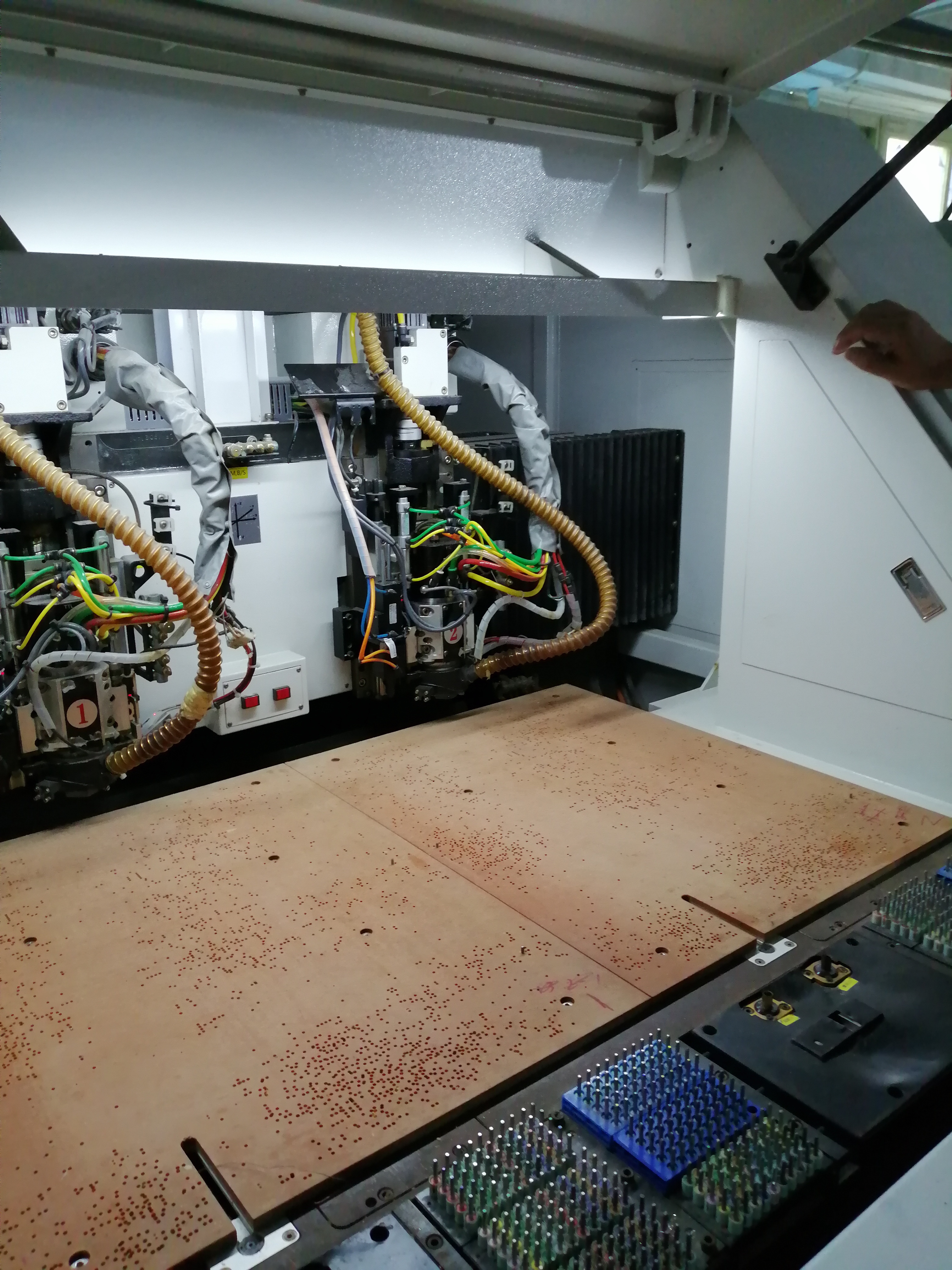
Today, we will introduce the machining method of micro holes: mechanical drilling.
In order to ensure high processing efficiency and hole quality, we reduce the proportion of defective products. In the process of mechanical drilling, the axial force and cutting torque should be considered, which may directly or indirectly affect the quality of the hole. The axial force and torque will also increase with the feed rate and the thickness of the cutting layer, so the cutting speed will increase, so the number of cutting fibers per unit time will increase, and the tool wear will also increase rapidly. Therefore, the service life of the drilling cutter is different for different sizes of holes. The operator should be familiar with the performance of the equipment and replace the drilling cutter in time. This is also the reason why the processing cost of micro holes is higher.
In the axial force, the static component FS affects the cutting of the transverse edge, while the dynamic component FD mainly affects the cutting of the main cutting edge. The influence of the dynamic component FD on the surface roughness is greater than the static component FS. Generally, when the diameter of prefabricated hole is less than 0.4mm, the static component FS decreases sharply with the increase of the diameter, while the dynamic component FD decreases flatly.
The wear of PCB bit is related to cutting speed, feed rate and slot size. The ratio of drill radius to glass fiber width has a great influence on tool life. The larger the ratio, the larger the cutting fiber bundle width and the greater the tool wear. In practical application, a 0.3mm drill tool life can drill 3000 holes. The larger the drill, the fewer holes to be drilled.
In order to prevent delamination, hole wall damage, stain and burr during drilling, we can first place a 2.5mm thick backing plate under the lamination, place the copper clad plate on the backing plate, and then put an aluminum sheet on the copper clad plate. The role of the aluminum sheet is:
- The protective plate surface will not be scratched.
- Good heat dissipation. The drill bit will generate heat when drilling.
- Buffering / drilling guide function to prevent deviation. The method to reduce burr is to use vibration drilling technology. Hard alloy bits are used for drilling, with good hardness. The size and structure of tools also need to be adjusted.

 Jan. 07, 2023